Use acoustic imaging to establish suitable structure and target context in dark or turbid water.
OPTICAL · IMAGING SONAR · MULTIBEAM · 3D
High-Resolution Underwater Imaging and Mapping.
Clarity where vision stops.
Ven-Tech delivers Underwater Imaging and Mapping across Canada for submerged infrastructure, seabed terrain, targets and difficult inspection environments.
4KOptical records
3DMapped surfaces
QATraceable checks
From difficult access to usable evidence
See the asset.
Map the context.
High-resolution Underwater Imaging and Mapping connects optical condition, acoustic geometry and project references in one deliberate field workflow.
No single sensor answers every underwater question. Cameras capture visible condition and colour when water clarity, lighting and stand-off permit. Imaging sonar provides acoustic awareness in darkness or turbidity. Multibeam systems can produce dense observations for positioned surfaces, structures and terrain when calibration and reference requirements are controlled.
Ven-Tech starts with the decision the client must make. The team defines the minimum feature or target, required coverage, reference system, dimensions, change question and deliverable before selecting an ROV, USV, vessel and sensor package.
Results are reported with method and limitations. Optical quality, acoustic resolution, positioning and map accuracy all change with environment, range, geometry, sound speed, motion, control and processing. Where one method leaves uncertainty, Ven-Tech can coordinate a complementary sonar, video, photogrammetry, survey or direct-inspection response.
Mission-specific sensor selectionField coverage verificationEngineering-ready outputs
Relate selected imagery, targets and surfaces to the agreed project reference and asset geometry.
Support selected depths, dimensions, profiles, clearances and volumes with documented controls.
Preserve a spatial record for future maintenance, construction or change review.
Underwater Imaging and Mapping capabilities
Multiple sensors.
One coherent record.
Ven-Tech configures Underwater Imaging and Mapping around the environment, minimum feature, required coverage, reference and intended decision—not around one fixed platform.
 01↗
01↗Multibeam imaging sonar
Capture acoustic images and project-selected three-dimensional surfaces around submerged structures, targets and terrain. High-frequency systems can provide useful close-range definition when suspended solids or darkness prevent dependable optical viewing.
Explore capability →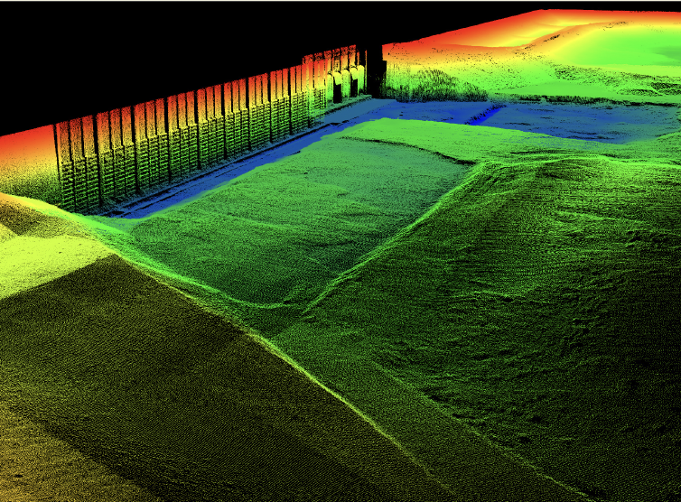 02↗
02↗High-resolution optical imaging
Collect controlled video and still imagery with ROV-mounted cameras, deliberate lighting, stable stand-off and project-selected colour or scale references. Optical records support condition review wherever visibility and access are suitable.
Explore capability →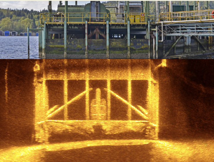 03↗
03↗Bathymetry & 3D surfaces
Combine positioned acoustic observations with motion, heading, depth, sound-velocity and water-level information as required to build point clouds, terrain models, contours, profiles and project-selected bathymetric products.
Explore capability →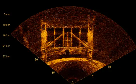 04↗
04↗Low-visibility asset inspection
Use imaging sonar to maintain situational awareness and inspect suitable intakes, outfalls, piles, walls, gates, conduits and submerged components where a camera alone cannot establish complete context.
Explore capability →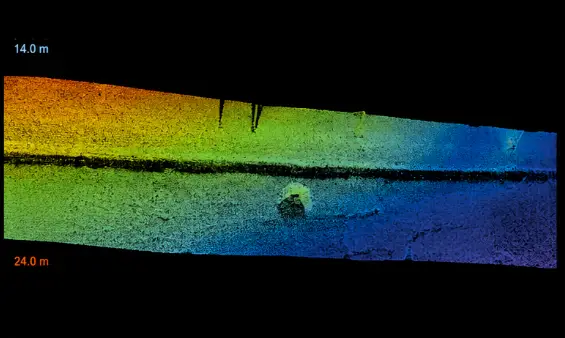 05↗
05↗Target location & geometry
Locate suitable objects, hazards, debris, scour features and structural elements relative to the selected platform and reference system. Target dimensions and position are reported with method, confidence and limitations.
Explore capability →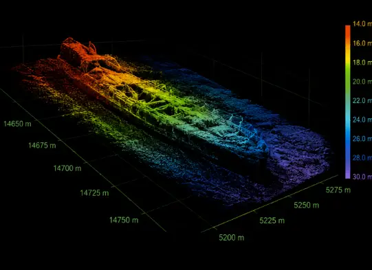 06↗
06↗Condition & change comparison
Create an initial spatial record and compare later project-selected datasets for sediment movement, scour, construction progress, deformation, obstruction or other observable change when acquisition geometry is sufficiently repeatable.
Explore capability →Acoustic visibility
When cameras lose sight.
Sonar keeps context.
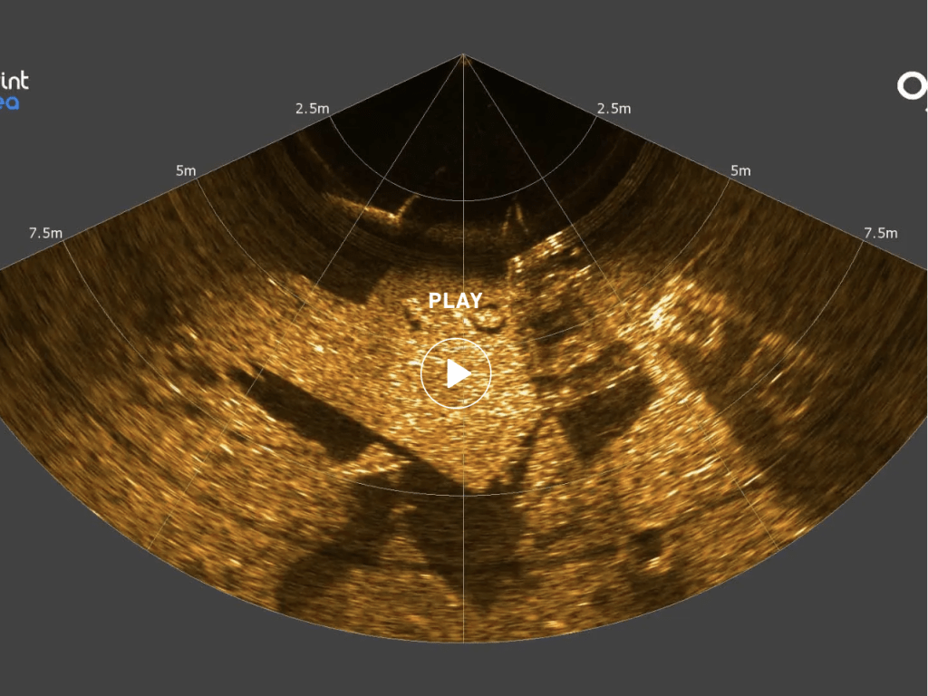
Imaging sonar does not make every target obvious. Useful interpretation still depends on range, frequency, geometry, stability, acoustic shadow, target orientation and operator review.
- 01 Select range and frequency for the target
- 02 Control sensor position and viewing geometry
- 03 Correlate sonar with optical or survey evidence
- 04 State confidence, gaps and limitations
Platforms & sensor systems
Close to the asset.
Positioned across the site.
Underwater Imaging and Mapping can move from detailed ROV inspection to wide-area surface mapping through a coordinated set of platforms, sensors and processing controls.
 01
01CLOSE RANGE / MANOEUVRABLE
ROV imaging platforms
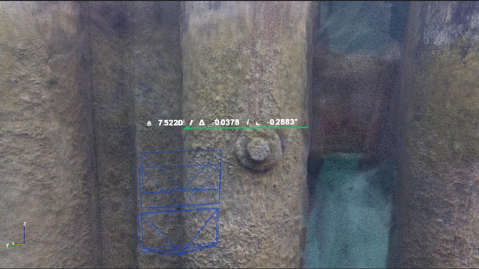
ROVs carry optical cameras, lights, imaging sonar, depth and project-selected positioning or measurement tools close to the asset. This geometry can improve detail and access beneath structures or inside suitable submerged spaces.
 02
02POSITIONED / WIDE AREA
USV & survey vessels
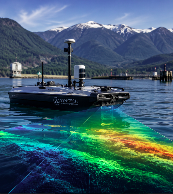
USVs and crewed vessels support repeatable survey lines for multibeam bathymetry, side-scan sonar and surface-positioned mapping. Platform choice follows water depth, sea state, traffic, payload, endurance and safe recovery.
 03
03TURBID / STRUCTURAL
Close-range sonar systems
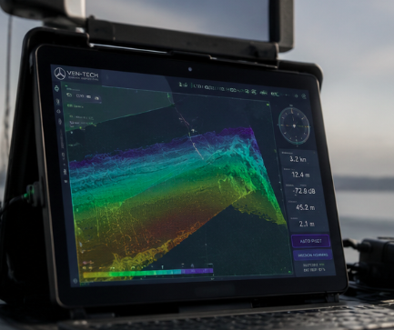
High-frequency imaging and multibeam sonar can be mounted close to piles, walls, gates, pipes and targets to strengthen acoustic definition. Range, frequency, field of view and mounting geometry are selected around the smallest feature of interest.
 04
04CORRELATE / VERIFY / REPORT
Processing & interpretation
Navigation, motion, sound speed, sonar, optical media and project references are reviewed together. Processing turns raw observations into cleaned imagery, point clouds, surfaces, annotations and reports with traceable checks.
Six-stage imaging workflow
Plan the evidence.
Control the coverage.
The Underwater Imaging and Mapping workflow keeps scope, HSE planning, acquisition, field quality review, processing and reporting connected from the first project question through final delivery.
Discuss your imaging scope ↗Define the decision
Confirm the asset, minimum feature or target, required coverage, dimensions, coordinate reference, change question, intended use and final deliverables before selecting a sensor.
Understand the environment
Review drawings, depth, visibility, access, current, turbidity, traffic, hazards, acoustic interference, surface conditions and known obstructions that affect platform and sensor geometry.
Match platform and sensor
Select ROV, USV or vessel deployment; optical, imaging-sonar or multibeam payloads; positioning; motion; sound-velocity control; lighting; scaling and field-quality checks.
Monitor coverage live
Follow planned lines or inspection routes while reviewing sonar range, image focus, overlap, navigation, density and coverage. Reacquire gaps or uncertain features before leaving the site.
Clean, align and verify
Apply the agreed navigation, motion, sound-speed, water-level and image corrections; remove unsuitable returns; review residuals and cross-check dimensions, targets and coverage.
Build the usable record
Issue the selected imagery, video, maps, point clouds, surfaces, profiles, measurements, annotations and technical report with references, quality checks and known limitations.
Underwater mapping deliverables
Field data shaped
for decisions.
Underwater Imaging and Mapping deliverables are agreed before mobilization so sensor range, resolution, positioning, coverage and processing support the owner, engineer, regulator or maintenance team who will use them.
Sonar imagery
High-resolution acoustic frames, mosaics or review exports for structures, terrain and targets.
Optical media
Indexed video, still images, inspection observations and project-selected annotations.
Point clouds
Cleaned XYZ, LAS, LAZ or selected point formats with coordinate and quality information.
3D surfaces
Bathymetric grids, meshes, digital terrain models and colour depth visualizations.
Plans & profiles
Contours, sections, route sheets, elevations and project-selected CAD or GIS drawings.
Measurements
Agreed clearances, depths, dimensions, areas, volumes or change values with method stated.
Target register
Positioned targets, observations, screenshots, classification, confidence and follow-up status.
Technical report
Scope, systems, references, acquisition, processing, quality review, results and limitations.
About Ven-Tech Subsea
Technology in the water.
People behind the evidence.
The About Ven-Tech film introduces the survey, robotics, diving, reservoir and inspection teams behind difficult field acquisition across Canada.
ABOUT VEN-TECH / 2025
One accountable project team
See the people, platforms and field disciplines connecting safe access, controlled acquisition, data quality and client-ready reporting.
Learn more about Ven-Tech ↗Resolution, reference & intended use
High resolution.
Defined confidence.
A sharp image and a reliable map are not the same thing.
NOAA explains that multibeam sonar sends multiple simultaneous beams and derives bathymetry from travel time, while backscatter records echo intensity. The International Hydrographic Organization’s S-44 standard and Canadian Hydrographic Service guidance connect survey quality to intended use, feature detection, control and documented procedures.
Ven-Tech applies project-appropriate checks rather than implying every inspection is a charting survey. The scope defines whether the result is qualitative imagery, relative geometry, positioned mapping or a survey product, and the report records references, processing, quality evidence and limitations.
Sensor geometry
Match frequency, range, field of view, stand-off, line spacing and overlap to the minimum feature and coverage.
Position & motion
Control applicable navigation, heading, attitude, depth, offset, time and reference-system observations.
Water corrections
Apply project-selected sound-speed, water-level, refraction or optical controls appropriate to the method.
Quality verification
Review gaps, density, cross-checks, dimensions, residuals, target confidence and intended-use limitations.
HSE · QUALITY · OPERATIONAL CONTROL
Remote access.
Controlled acquisition.
Robotic and remote methods can reduce exposure, but deployment still requires launch and recovery planning, electrical and mechanical controls, vessel or worksite coordination, tether management, communications, environmental limits, data custody and emergency provisions.
BCCSA COR® CertifiedISNetworld Member ContractorISNetworld ESG BadgeAvetta ApprovedCognibox CertifiedAlcumus SafeContractorProject-specific HSE plansCalibrated sensor workflowsField coverage reviewTraceable processingData quality checksATHENA™ operational framework
Underwater Imaging and Mapping applications
Critical assets.
Difficult visibility.
Underwater Imaging and Mapping supports owners and engineering teams responsible for submerged infrastructure, construction, maintenance, navigation, environmental programs and emergency investigation.
01Dams, spillways & gates↗
02Reservoirs, intakes & outfalls↗
03Ports, berths & marine terminals↗
04Bridge piles & foundations↗
05Pipelines, cables & crossings↗
06Dredging & construction support↗
07Environmental & habitat programs↗
08Search, debris & obstruction surveys↗
Underwater Imaging and Mapping FAQ
Plan the method
with confidence.
These answers are a practical starting point. Ven-Tech confirms sensor suitability, access, HSE planning, quality controls and deliverables for the actual asset and environment.
What is Underwater Imaging and Mapping?+
Underwater Imaging and Mapping combines suitable optical cameras, imaging sonar, multibeam sonar, positioning and processing to document submerged structures, targets and terrain. The selected platform and sensors depend on visibility, access, water depth, feature size, required reference and final decision.
Can imaging sonar work when the water is turbid?+
Imaging sonar uses sound rather than visible light, so it can provide useful acoustic images in dark or turbid water where cameras cannot establish dependable visual detail. Resolution still depends on sonar frequency, range, mounting geometry, target orientation, noise and operating conditions.
What is the difference between imaging sonar and bathymetric mapping?+
Imaging sonar emphasizes acoustic visualization and situational awareness. Bathymetric mapping emphasizes positioned depth observations and surfaces. Some multibeam systems support both objectives, but acquisition geometry, positioning, calibration, processing and deliverables must still be designed for the intended use.
How accurate are underwater maps?+
Accuracy is project-specific. It depends on positioning, motion, heading, depth, sound speed, water level, system calibration, range, geometry, environmental conditions and processing. Ven-Tech defines applicable controls and reports the achieved quality and limitations instead of promising one universal accuracy.
Can Ven-Tech combine sonar and optical video?+
Yes. Sonar can establish geometry, guide an ROV or locate targets, while optical video and stills provide visible condition and colour where water clarity permits. Correlating both records can create stronger asset context than either sensor provides alone.
What platforms can carry the sensors?+
Ven-Tech can configure project-selected sensors on ROVs, USVs, crewed survey or work vessels and other controlled platforms. Selection follows access, depth, current, sea state, traffic, payload, communication, endurance, launch and recovery, and HSE requirements.
What deliverables are available?+
Deliverables can include indexed video, still images, sonar imagery, mosaics, target registers, point clouds, bathymetric grids, meshes, contours, profiles, CAD or GIS exports, measurements, change products and a technical report describing references, quality and limitations.
What information is needed for a proposal?+
Provide the asset and location, dimensions, drawings, water depth, visibility, access, operating state, hazards, currents, minimum target or feature, required coverage, coordinate needs, schedule and desired deliverables. Previous surveys and inspection records help define the method.
Start with the decision
Need clearer underwater
asset intelligence?
Send the asset, location, dimensions, depth, visibility, access, known hazards, minimum feature, required coverage, coordinate needs and desired deliverables. Ven-Tech will help define a practical Underwater Imaging and Mapping approach.